

Introduction: FM Radio


Recently, I came across RDA5807 module which is an FM Radio Tuner in a very tiny package. It is very cheap and uses I2C protocol for communication which means that only two wires will be required to talk to the IC. Less wiring!
My mom used to listen to the radio every day while cooking food before the radio died. I wanted to surprise her with a radio which I built myself. In this Instructables, I will show you how I interfaced RDA5807 IC with an Arduino. To make it look good, I designed an enclosure and 3D printed it. I'm new to 3D designing so it will be a simple design. No fancy stuff.
Let's get started!
Supplies
1x Arduino Nano
1x 3W Speaker
1x PAM8403 Audio Amplifier Module
2x 6x6 Tactile Switches
1x 100k Potentiometer
1x DC Power Socket
Optional:
3D Printer
Step 1: The Plan
The plan is to keep everything simple and neat. No fancy stuff.
We will be using Arduino Nano as the brain for our project. The hard work of communicating with the module has already been done. Make sure you install the Radio library. There are many features which you can play with. Note: The library also works for SI4703, SI4705 & TEA5767.
One push button at the front will be used to put the radio in "Frequency Selection" mode and the other push button to select the frequency. A Pot will be used to scroll through the preset frequencies (which can be set in the code depending on your location).
An OLED Display will be used to show the frequency at which it is tuned in.
The output audio signal of the radio module is very low and is not sufficient to drive a 0W speaker. PAM8403 module will be used to amplify the audio signal. There are many versions of this module. I went with the one which has a pot for volume control as well as ON/OFF switch.
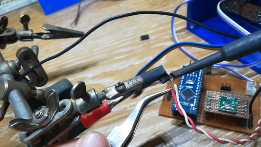
Step 2: Preparing the FM Radio Module


As you can tell by looking at the picture, it is very, very tiny! On top of that, the pad spacing of the module is not breadboard/perfboard friendly.
We have to make a breakout board for it. Cut a small piece of perfboard about the size of the module. Make sure there are at least 5 holes on each side. Solder male header pins as shown in the picture. Next, place the module on the board and solder thin wires between pads on the module and header pins. I used the trim outs of the component legs.
Step 3: Making the Enclosure


I am completely new to 3D designing and this is by far the most I have designed. The enclosure is designed in Fusion 360 and printed on Creality Ender 3 printer. I have attached all the .STL files which I have used.
I painted the Front Plate in white as I have only one color of filament.
I inserted the 'M3 Threaded Inserts' in the holes on the outer body using a soldering iron. It was quite satisfying!
Glue the Inner Rim inside the Outer Body using super glue.
Also, make a 6mm and 2mm hole in the 'Back Plate' for the knob of the amplifier and antennae respectively. I forgot to add those while designing.


Step 4: Preparing the Circuit Boards


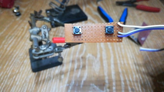

We need to make two circuit boards. One will be the main board with Arduino and FM Module and another one for the push buttons which will be mounted on the front plate.
I have used connectors using Male and Female Header pins for each component so that it can be connected/disconnected with ease. You can skip this step if you want.
Do the wiring as per the schematic.

Step 5: Time for Coding
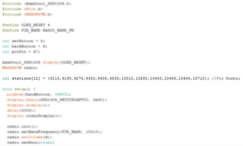

The code has been attached here. Download the .ino file and open it in Arduino IDE. Before you upload, there are two things you need to modify.
- The number of radio stations and their frequencies will change. A quick Google search will let you know the Stations and their frequencies. Once you have listed them out, add them in the 'stations[]' array as shown in the picture. You have to omit the decimal point. For example, 9110 means 91.10 MHz, 10110 means 101.10 MHz and so on.
- Also, enter the total number of stations in between the square brackets. In my case, I have got 12 stations inside the array. Hence, stations[12].Subtract 1 from the total number of stations and enter it in the code as shown in the second picture. 11 in this case.
I know there is a better way, but I ended up having many errors instead!
And, upload the code!
Attachments
Step 6: Putting Things Together


Hot glue the OLED display and speaker in place on the front plate.
Place the 3D printed buttons in their position, add a drop of super glue on the tactile switches and place the circuit board on top of the buttons making sure that the buttons and switches line up.
Screw in the potentiometer on the front plate.
Apply a generous amount of super glue on the inner rim and place the entire front plate with all the components on the rim.
Make all the connections of the components with the main circuit board. Connect the audio output from the radio module to the amplifier which is mounted on the back plate.
Put a dab of hot glue around the connectors to act as a strain relief.
Screw on the back plate using M3 screws.
Finally, cut the hot glue stick into 4 circles with a thickness of around 2-3mm and glue them at the bottom as shown. They will serve the purpose of rubber feet.
You're done!
Step 7: Enjoy!
Power up your radio using 5V supply. If you are not able to find a 5V one, use 7805 voltage regulator with 12V as input.
Thank you for sticking till the end. Hope you all love this project and learned something new today. Let me know if you make one for yourself. Subscribe to my YouTube channel for more upcoming projects. Thank you once again!


