

Introduction: Retro LED Strip Audio Visualizer

As a musician and electrical engineering student, I love any project that intersects these two fields. I've seen some DIY audio visualizers (here, here, here, and here), but each had missed at least one of the two goals I established for myself: a professional build quality and a relatively large display (a wimpy 8*8 LED matrix would not suffice here!). With some vintage flair, and sitting at 40" x 20", this audio visualizer accomplishes both of those goals.
Apologies in advance for vertical photos. A lot of them were taken for social media.
Step 1: Parts List

I had several of these parts lying around already. The links are purely for reference. Please don't buy unnecessarily expensive components.
Electronics
- WS2811 60LEDS/m @ 5m, IP30 (Non-Waterproof), Addressable - These were cheaper then WS2812 at the time. You have some leeway here but make sure the dimensions are correct and that you can actually talk to the LEDs. Also note that WS2811s are 12V while WS2812s are 5V.
- 9 x 3-Pin JST Connectors + Receptacles
- DC 12V 20A (240W) Power Supply - I initially planned on doing 2 LED strips, and wanted a blow-your-house-down speaker set. Each light strip is 90W in worst-case scenario (I haven't measured to confirm), which left me ~60W for speakers + amplifier. The 15A option was only $4 less anyway.
- Power cord (3 Prong)
- Arduino Uno - I had an R3 lying around so I used that. You may be able to find a cheaper option from one of the knockoffs or another vendor.
- TRRS Breakout - For aux input
- L7805 5V Regulator - Any 5V regulator that accepts a 12V input will work.
- 330 nF, 100 nF capacitors - per L7805 datasheet
- 2 x 10kR, 2 x 1kR, 2 x 100 nF capacitors - for audio input biasing
- Stereo Receiver - any vintage stereo receiver will work as long as it has aux input (3.5mm or RCA). I picked up a Panasonic RA6600 off craigslist for $15. I recommend checking Goodwill, craigslist, and other thrift stores for similar.*
- Speakers - Not BT speakers. Just a speaker set. Pay attention to what impedance is compatible with your receiver. I found a set of 3 20W (=loud) speakers at Goodwill for $6, and that came with a "center" and two "front" speakers.
- Logitech BT Audio Adapter - this device can stream audio out to the stereo speakers and to your circuit
- RCA male to RCA male cable
- Aux cord
Hardware
- 2x6 (8ft) - Not pressure treated. Should be ~$6 or less at HD or Lowe's
- 40% Light Transmission Acrylic - I ordered 18" x 24" x 1/8", and it was technically 17.75" x 23.5". Keep it in the wrapping when you go to laser cut.
- Wood Stain - You only need a small can. I used Minwax red mahogany and it came out very nice. I definitely recommend a dark tone. I originally tried provincial and it didn't look as nice.
- Lacquer - First off, check out this video by Steve Ramsey and decide for yourself what works best. I got a spray can of semi-gloss (no gloss was available) and honestly, it didn't do that much. But I also only did one coat due to time constraints.
- 40 x 1/2" Wood screws - I had round head available to me but I recommend using flat top if you can. I don't think that would interfere with the build quality but feel free to ask anyone more familiar with woodworking first.
- Scrap wood, gorilla glue, hot glue, solder, wire, and command strips (velcro style, 20 medium or 10 large)
* I plan on building a sound bar to make this project entirely "from scratch," which will replace 9-13 above. I hope to update this instructable with that by the end of the summer.
Step 2: Prototyping

This section is not something you need to complete, but I do want to show what the project looked like as it went along.
Here, I taped down LEDs in the snake pattern, and was experimenting with light diffusion via trash bag layered over top of itself (I highly recommend that as an alternative to the acrylic if you are trying to cut costs. Though you'll have to attach it some different way).
A 10x10 setup worked for me, but you may prefer 8x12 or 7x14. Feel free to experiment. Before I had my stereo, I found an amplifier and hooked it up in my breadboard, and before that, I played audio from my laptop to the circuit for audio analysis and simultaneously hit "play" on my phone to hear it.
I'm a huge believer in measure twice, cut once. So whatever you do, follow that guide and you'll be set.
Step 3: Circuitry + Code


Code is available on GitHub.
Breadboard, solder to a perfboard, or design your own PCB. Whatever works best for you here, do it. My demo here is running on a breadboard, but when I build the soundbar I will transfer everything to a PCB. To get power from the adapter, cut off the female end and remove the black insulation. Strip enough of the actual cables to screw it to the adapter terminals. Always be careful working with AC! Other than that, just a few things to note here.
- Ground Paths
One other thing is to make sure your ground paths are good. You need ground from the adapter to Arduino to aux input, which will also connect to the ground on the Logitech BT receiver and from there the ground on the stereo. If any one of these is a broken or bad connection, you will get a very noisy audio input and hence a very noisy display. - Audio Input Biasing
Audio played over aux cord, from your phone or laptop or wherever, will play at -2.2 to +2.2V. Arduino is only capable of reading 0 to +5V, so you need to bias the audio input. This can be accomplished efficiently with op amps, but if power consumption is not an issue (perhaps you bought a 240W power supply?), it can also be accomplished with resistors and capacitors. The values I chose were different because I had no 10uF capacitors on hand. You can play around with the simulator to see if what you choose will work. - Fourier Transforms
Any project that uses Fourier transforms is going to have a background section discussing them. If you already have experience, great! If not, all you need to understand is that they take a snapshot of a signal and return information about what frequencies are present in that signal at that point in time. So if you took the Fourier transform of sin(440(2*pi*t)), it would tell you that a 440Hz frequency is present in your signal. If you took the Fourier transform of 7*sin(440(2*pi*t)) + 5*sin(2000(2*pi*t)), it would tell you that both a 440Hz and 2000Hz signal are present, and the relative degrees to which they are present. It can do this for any signal with any number of component functions. Since all audio ever is just a sum of sinusoids, we can take the Fourier transform of a bunch of snapshots and see what is really going on.
You'll see in the code that we also apply a window to our signal before taking the Fourier transform. More on that can be found here, but short explanation is that the signal we actually end up giving the transform kinda sucks, and windows fix that for us. You're code won't break if you don't use them, but the display won't look as clean.
There may be better algorithms available (YAAPT, for instance), but following principles of KISS, I elected to use what was already available, which is several well-written Arduino libraries for the Fast Fourier Transform, or FFT. - Can the Arduino really process everything in realtime?
For everything to appear in realtime, the Arduino needs to grab 128 samples, process that FFT, manipulate the values for the display, and update the display very quickly. If you wanted 1/16th note precision at 150bpm (close to the upper end tempo of most pop songs), you would need to process everything in 100msec. Additionally, the human eye can see at 30FPS, which corresponds to 30msec frame lengths. This blog post did not give me the greatest confidence, but I decided to see for myself if Arduino would hold up.
After my own benchmarking, I was very proud of my R3. The calculation phase was by far the limiting factor, but I was able to process a 128 length FFT of UINT16s in only 70msec. This was within audio tolerances, but over double the visual constraint. On further research, I found Arduino FHT, which takes advantage of FFT symmetry and only calculates the real values only. In other words, it's about 2x as fast. And sure enough, it brought the entire loop speed to ~30msec.
One other note here on display resolution. A length N FFT sampled at Fs Hz returns N bins, where the kth bin corresponds to k * Fs/N Hz. The Arduino ADC, which is reading the audio input and taking samples, normally runs at ~9.6kHz. However, the FFT can only return information about frequencies up to 1/2 * Fs. Humans can hear up to 20kHz, so we would ideally want to sample at >40kHz. The ADC can be hacked to run a bit faster, but nowhere near there. The best result I saw without losing stability was at a 14kHz ADC. Additionally, the largest FFT I could process to still get a realtime effect was N=128. This means each bin represents ~109Hz, which is fine at higher frequencies but bad on the low end. A good visualizer tries to reserve an octave for each bar, which corresponds to separations at [16.35, 32.70, 65.41, 130.81, 261.63, 523.25, 1046.50, 2093.00, 4186.01] Hz. 109Hz means the first 2.5 octaves are all in one bin. I still was able to get a good visual effect, in part by taking the average of each bucket, where a bucket is a group of bins between two of these bounds. I hope this isn't confusing, and the code itself should clarify what is really going on, but feel free to ask below if it doesn't make sense.
Step 4: Assembly


As I stated earlier, I wanted something with professional build quality. Originally I started wood gluing slats together, but a friend (and skilled mechanical engineer) suggested a different approach. Note that a 2x6 is really 1.5" x 5". And please be careful working with any of the below machinery.
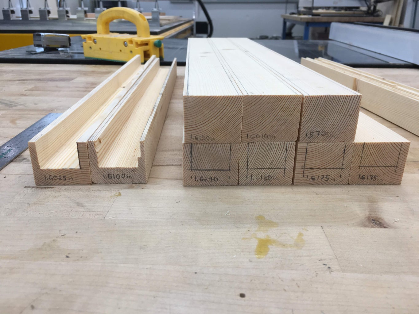
- Take your 2x6x8 and sand if needed. Cut it into 2" x 6" x 22" sections. This gives you two slats to "burn" if you mess up.
- Take each 22" section and run it through a table saw longways to make 1.5" x ~1.6" x 22" slats. The last third may be difficult to cut on a table saw, so you can switch to a band saw. Just make sure everything is as straight as can be. Additionally, 1.6" is a guide, and can go up to 1.75". That's what my pieces were, but as long as they are all equal to each other it doesn't matter too much. The limiting factor is the acrylic at 18".
- On the end of the pieces, mark a U-shape that is 1/8" in on either side and slightly more than 3/4" deep. NOTE: If you use a different acrylic, the depth will change. At < 3/4", my acrylic does not diffuse light at all. At slightly more, it diffuses completely. You want to avoid any "beadiness." I found this Hackaday post to be a good reference, but getting the perfect diffusion is very difficult!
- With a tabletop router, cut out that middle U all the way down the slat. The 22" is longer than you need, so don't worry about chipping the ends if you do. Routers can be tricky, but get a bit that is slightly wider than half the width of the U and be careful cutting more than 1/8" of material at a time. Repeat: Do not attempt to do it all in 2 passes. You will damage the wood and likely hurt yourself. Work with the router's rotation on cuts 1-4, and work against it on 5-8. This ensures that you have best control over the router's torque.
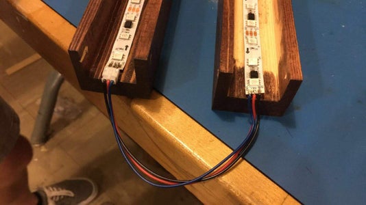
- Cut the LED strip into 30-LED sections (only every set of 3 LEDs is addressable). You'll probably need to desolder a few of the connections. Lay those strips along the tracks. One side should sit flush, and the other should have a little room for the JST receptable, which will sit flush. I unfortunately didn't get a picture of this, but see the attached diagram. Mark the length here, but don't cut anything yet.
- Measure the width of each slat. With this and the length from step 7, laser cut the acrylic into the 10 necessary rectangles. It's better to be slightly long than slightly short. If it gets burnt, wipe it down with isopropyl.
- Confirm that each acrylic slat sits at the same length that you marked in step 5, then cut the slat down to this length.
- You now need two bridge pieces to attach the acrylic. This allows for easy maintenance of light strips should anything arise. These pieces should be roughly [your width] - 2 * 1/8" long with 1/2" square faces, but they should fit a little tight. With these pieces firmly in place and flush with the front face of the slats, drill holes through the center of each bridge from the outsides of the slats. Do your best to make each drill even. Don't keep the bridges screwed in, but make sure they can be. Careful not to drive the screw down too far and split the wood.
- At this point, stain the slats and apply any finish.
- Now screw in the bridges. Make sure they are sitting flush! If not, you will need to add some kind of shim. Apply gorilla glue (preferred) or hot glue (which can double as a shim) to the bridges and attach the acrylic. Do not apply any adhesive along the slat itself.
- Solder JST receptacles to one side of all but one LED strip. Put them all on the same end as given by the marked arrows. Solder the wires of the JST plugs onto the other ends. You may need to strip more wire on each connector. Make sure the connections will be correct when plugged in! The adhesive on the back of the LEDs is terrible, so don't trust it. Lay the LEDs down the center track and glue them down with gorilla glue, paying attention to the indicated direction on the strips. Remember that you are snaking the whole thing.
- On the first slat, solder long enough wires to get power + ground from the adapter and the signal from the Arduino.
- Screw the slats and bridges back down. Attach command strips to the back (velcro style, 2 medium at top and bottom or 1 large in the center). Make all the necessary connections, and hang on the wall at ~3" apart. Enjoy the fruits of your labor.

Participated in the
Arduino Contest 2019


