

Introduction: Raspberry Pi Laser Scanner


The Laser Scanner is a Raspberry Pi embedded system device able to digitize objects into .obj mesh files for reproduction using 3D printing. The device does this by utilizing a line laser and an integrated PiCam to perform computer vision. The laser is positioned 45 degrees askew from the laser and projects a bright red line on one vertical slice of the object. The camera detects the slice’s distance from the center to give a mesh slice. The object is spun on the rotating tray and the process is repeated until the full object is scanned. The generated .obj file is finally emailed to the user, making the system fully standalone and embedded.
This Instructable will walk through how the device was built, some results, and future steps.
Step 1: Inspiration


As an avid maker, I have been 3D printing and solid modeling for several years now. I've worked with a lot of different prototyping tools from CNC routers to laser cutters to 3D printers. One device that my local makerspace has yet to buy has been a 3D scanner - and i can tell you why to.
The cheaper ones (a few hundred dollars) were unreliable, required perfect conditions, and still produced pretty shabby results. The expensive ones were... well, expensive, ranging up to several thousand dollars, making its function not worth it in many cases. On top of that, more times than not, I opt to take measurements and design a model from scratch than deal with the surface mesh generated from a scan.
Because of this, I wanted to build a budget standalone scanner to see how well I could scan an object using off the shelf components.
After doing some research, I saw that many 3D scanners utilized a rotating platform and then a variety of different sensors to measure distance from the center in order to build a rotational model. Many of these used dual cameras similar to that of the Kinect. I eventually stumbled upon the Yscanner which is a low resolution scanner making use of a laser. Looking at simplicity and feasibility, this laser technique, in which a laser is shined offset relative to a camera to measure distance from center, looked like a clear path forward.
Step 2: Tools and Parts
Parts:
- Raspberry Pi $35.00
- Raspberry Pi Camera V2 $30.00
- LEDs, Resistors and Wires
- 3D printing filament
- 12x12x0.125 wood sheets
- M3 hardware
- Stepper Motor - $14
- Line Laser - $8
- LN298 Stepper Motor Drivers - $2.65
- Metal Pushbutton - $5
Tools:
- Soldering iron
- Laser cutter
- 3D printer
- Screwdriver
- Pliers
Step 3: High Level Design

The central component in this design is the line laser that projects upon a vertical slice of the objects. This projection could be captured on the picamera, have its perspective corrected, and then filtered prior to image processing. In image processing, the distance between each segment of the line from the center of the object could be collected. In radial coordinates, this picture would yield both the r and z components. The third dimension, Θ, is then achieved by rotating the object to a new slice. This concept is shown in the first figure.
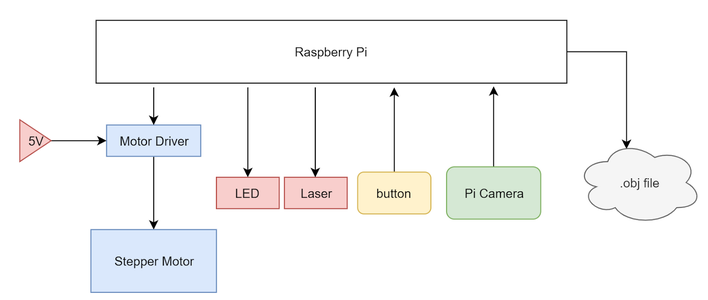
To perform the described actions above, I utilized a Raspberry Pi as our central computing unit. I attached a stepper motor and a motor driver to the Pi, powered by an external 5V supply and controlled by the Pi’s GPIO pins. A line laser was put on the 3.3 V line on the Pi and a PiCam was attached to the camera input on the Pi. Lastly, a simple pulled down button was installed and a status LED to indicate to the user what state the system is in. The full system is summarized in a system block diagram.
From the start, it was planned to house the electronics in a laser cut box held together with T-slots and M3 hardware. The electronics would be hidden from sight in a bottom compartment and a lid would allow for easy access to object placement on the rotating tray. This lid is necessary in order to minimize the amount of light that leaks into the system, as this external light can produce noise in the final scan.
Step 4: Hardware


As seen above, before I began laser cutting or 3D printing, I used Autodesk Fusion 360 to make a detailed 3D model of our design. As an overview, the device is a simple box with a lid with laser cut hinges. There are two main layers of the device: the electronics bed and the main bed, with holes for wires to run between the two layers.
The majority of our box was manufactured with a laser cutter, with designs being produced in Fusion 360 and cut on an Epilog Zing 40 W laser cutter. Our designs are shown in the figures above. From top left moving right, the pieces are the main bed, the electronics bed, two pieces for the lid, the back piece, the front piece, and the two side pieces. In the main bed, there are three main cutouts: one for mounting the stepper motor, one to route wires from the laser, and one to route the PiCam’s wide cable. The bed piece has mounting holes for securing the Pi, breadboard, and motor driver and a larger cutout to access the stepper motor. The lid pieces snap together simply to form the triangular piece seen above and the hinge is a simple extrusion that is the width of the diameter of the hole of the side boards. The back piece and one of the side pieces have slots on the side so that the ports of the Pi (HDMI, USB, Ethernet, Power) can be accessed easily. The front is a simple piece that I eventually made holes in with a hand drill to mount the button and LED.
As seen on all the pieces, our parts are held together by M3 hardware using T-Joints and slots. This is a method of holding laser cut pieces orthogonally and securely. The fins of pieces line up with the slots other pieces and the t-shaped cut on the edges give space for an M3 nut to be jammed into them without spinning. This allows us to then use an M3 screw to lock the pieces together with very little wiggle room without having the assembly be fully permanent.
I chose to do the majority of our pieces with a laser cutter due to its speed and ease. However, I still had to 3D print some pieces due to their 3D geometry that would be more difficult to create on the cutter. The first piece was the line laser holder. This piece was to be mounted on the main bed at 45 degrees from the camera’s view and have a hole such that the laser could be snuggly friction fit into it. I also had to create a motor mount because the motor’s shaft was so long. The mount friction fit into the laser cut pieces and lowered the plane that the motor was attached to such that the rotating platform was flush with the main bed.
Step 5: Electronics

The wiring hardware of this project was very simple as the 3D scanner did not require too many peripherals. A motor, button, LED, laser, and camera needed to be connected to the Pi. As shown, I made sure to connect resistors in series with each pin we used in order to protect the pins. One GPIO pin was dedicated to controlling the status LED, which would light up when the device was ready to be used and pulse with PWM when the device was operating. Another GPIO pin was connected to a pulled-up button, registering HIGH when the button was not pressed and LOW when the button was pressed. Lastly, I dedicated four GPIO pins to driving the stepper motor.
Since our motor only had to step a certain extent without requiring control of speed, we opted for a simpler stepper motor driver (L298N) that simply steps up the control lines to feed into the motor’s inputs. To learn about how to operate the stepper motors on a very low level, we referred to both the L298N data sheet and the Arduino library. Stepper motor’s have a magnetic core with pertruding fingers of alternating polarity. The four wires are wrapped to control two electromagnets which each power every other opposing finger in the motor. Thus, by switching the polarity of the fingers, we are able to push the stepper one step. With this knowledge of how steppers worked from a hardware level, we were able to control the steppers much more easily. We opted to power our stepper motor off of a 5V power supply in the lab rather than the Pi because of its maximum current draw of about 0.8 A, which is more than the Pi could supply.
Step 6: Software


The software for this project can be broken down into four main components that interact together: Image Processing, Motor Control, Mesh Creation, and Embedded Functions.
As a summary of the software, we can look to the first figure. As the system boots, the .bashrc automatically logs into the Pi and starts running our python code. The system lights up the status light to let the user know that it has been booted correctly and waits for the button press. The user can then place the item to be scanned and close the lid. After pushing the button, the LED pulses to let the user know the device is working. The device will loop between image processing and motor control until the full rotation is complete and all object data is collected. Finally, the mesh is created and the file is emailed over to a preselected email. This restarts the cycle and the machine is ready to perform another scan at the press of a button.
Image Processing
The first thing implemented was processing a captured image in order to extract the information stored in the image into a form that could be used to create an array of points in space. To do this, I started by taking a picture of the object on the platform along with all the background noise created by the laser shining onto the back of the box and dispersing. This picture had two main problems in its raw form. First, the object was viewed at an angle with an elevated perspective and second, there was a lot of background noise. The first thing I needed to do was account for this viewing angle because using the photo as is would not allow us to determine a consistent object height. As seen in the second figure, the height of the upside down “L” shape is consistent; however due to one side being longer than the other they appear to have different heights at the edge closest to the viewer.
To fix this, I had to transform the workspace in the image into a rectangle from the trapezoidal shape it was in previously. To do this, I used the code provided by this link, which when given an image and four points, crops the image between the four points and transforms the cropped image to compensate for the perspective. This transformation uses the four points to create a rectangle instead of a trapezoid type shape as seen in the third figure.
The next problem that needed to be solved was that of background noise in the form of outside light and light being reflected by the laser itself. To do this I filtered the light using the inRange() function of OpenCV. I set the threshold to only pick up red light at a certain level. To get the correct value, I started with a lenient threshold and kept increasing the threshold level until the only light being picked up was the laser light on the object being scanned.
Once I had this image, I found the brightest pixel in each row to get a line of one pixel per row that bordered the left most side of the laser line. Each pixel was then converted to a vertex in 3D space and stored in an array, as described in the mesh creation section. The results of these steps can be seen in the fourth figure.
Motor Control
After being able to successfully process a single image to get the slice of the object, I needed to be able to rotate the object to take a new picture with a different angle. To do this, I controlled the stepper motor below the platform that the object being scanned sits on. I built a foundation of our stepping function by creating a variable to track the state of the motor and microstepping by toggling each of the four motor inputs.
Mesh Creation
To create a mesh from all the processed images, I first had to convert each white pixel in the processed image into a vertex in 3D space. Because I am collecting individual slices of the object with cylindrical symmetry, it made sense to start to collect cylindrical coordinates. This made sense as the height of the picture could represent the z-axis, the distance from the center of the rotating table could represent the R-axis, and the rotation of the stepper motor could represent the theta-axis. However, because I stored our data in cylindrical coordinates, I had to convert each of these vertices over into cartesian coordinates.
Once these vertices were created, they were stored in a list and said list was stored in another list that contained the vertex lists created for each image captured. Once all the images were processed and converted to vertices, I had to select the vertices that I actually wanted represented in the final mesh. I wanted the top vertex and the bottom vertex to be included and then based on the resolution I picked an evenly spaced number of vertices to use for each image. Because not all vertex lists were of the same length, I had to even them out by finding the list with the smallest number of vertices and removing vertices from all other lists until they were all even.
With the vertex lists created I was now able to create a mesh. I chose to format our mesh by the .obj file standard as it is simple and 3D printable.
Embedded Function
After the device was functional, I polished it by adding full embedded functionality. This meant removing the keyboard, mouse, and monitor, and having it wirelessly send us the .obj file after finishing processing. To start, I changed the .bashrc code to automatically log in and launch the main python program on startup. This was done by using sudo raspi-config and selecting “Console Autologin” and by adding the line “sudo python /home/pi/finalProject/FINAL.py” to /home/pi/.bashrc.
In addition to this, I also added a button and status LED for user input and output. The button would let the user tell the device when to start scanning and the LED would tell the user the state of the machine. If the LED is on, the device is ready to start a new scan. If the LED is pulsing, the device is currently scanning. If the LED is office, there is a software error, calling for a system restart. Lastly, I enabled the device to send the .obj file over email. This was done by using the smtplib and email libraries. This ability to send emails gave us a very convenient and wireless way to deliver the produced file to the user to access on many different platforms.
Step 7: Integration

After manufacturing the various pieces of the device, I assembled it together. The figure above shows in order:
(a) assembled box outside
(b) assembled box inside with camera and laser
(c) inside view of electronics bed
(d) back of the Pi with access to Pi ports and the 5V motor input
(e) push button with LED ring and status light in the front of the device
Step 8: Results


The laser 3D scanner was able to scan objects with decent precision. The objects’ features are distinct and recognizable and the parts were very easy to 3D print using a slicing software such as Repetier. The figures above show some sample scans of a piece of wood and a rubber ducky.
One of our biggest findings and successes that I discovered during testing was the consistency of the device. Throughout multiple trials of the same object, the scanner was able to produce a .obj file that was very very similar each time, even if we slightly altered the placement of the object. As seen in the three separate scans, they all look very similar, capturing the same details and same amount of detail. I was overall very impressed with our system’s consistency and robustness.
One of the variables I was really able to tune is the resolution of the scans. Because there are 400 steps in the stepper, I can choose how big each ΔΘ to dictate the angular resolution. By default, I have the angular resolution set to 20 iterations, meaning that each frame, the motor rotates by 20 steps (400/20 = 20). This was chosen mainly in the interest of time - it takes about 45 seconds to complete a scan this way. However, if I want a much higher quality scan, I can increase the number of iterations all the way up to 400. This gives many more points to construct the model with, making for a much more detailed scan. In addition to angular resolution, I can also adjust the vertical resolution, or how many different points I choose to poll along the laser slice. For a similar interest in time, I have this default set to 20 but I can increase it for better results. In playing with these parameters of angular resolution and spatial resolution, I was able to compile the results of different scans below in the last figure. Each label is formatted such that it is the angular resolution x spatial resolution. As seen in the default scanning settings, the features of the duck are recognizable but not detailed. However, as I increase the resolution, individual precise features begin to show, including the eyes, beak, tail, and wings on the duck. The highest resolution image took about 5 minutes to scan. Seeing this high of an achievable resolution was a very large success.
Limitations
Despite the successful results of the project, there are still a few limitations of the design and implementation. With the use of the laser comes a lot of issues with how the light disperses. Many objects I tried to scan that were either translucent, shiny, or very dark proved troublesome with how the light reflected off the surface. If the object was translucent, the light would be absorbed and dispersed, making for a very noisy reading of slices. In shiny and dark objects, the light would either be reflected or be absorbed to the point of which it would be difficult to pick up. Furthermore, because I am using a camera to capture the features of objects, its sensing is limited by its line of sight, meaning that concave objects and sharp angles are often blocked by other parts of the object. This is shown in our rubber duck example as the tail sometimes will lose its curvature in the scan. The camera can also only detect surface structures meaning that holes or internal geometries cannot be captured. However, this is a common problem that many other scanning solutions have as well.
Next Steps
Although I was happy with the results of our project, there were a few things that could be implemented to make it better. For starters, in the current state, the scan resolution can only be changed by changing the hard coded resolution variables in our code. To make the project more embedded, a resolution potentiometer could be included so the user could change the resolution without having to plug in a monitor and keyboard to the scanner. In addition, the scanner creates images that can sometimes look jagged. To fix this, mesh smoothing techniques could be implemented to smooth out irregularities and harsh corners. Lastly, I found that pixel coordinates do not scale well into the real world. The meshes I created were 6 to 7 times larger than the actual object. In the future it would be advantageous to implement a way of scaling meshes so they are more accurate to the real size of the object.
Step 9: Resources
I've included the code, STL files for printing, and DXF files for cutting for the entirety of the project.


First Prize in the
Raspberry Pi Contest 2020


