

Introduction: Using Wood to Fuel a Generator! (How to Build a Wood Gasifier W/Demonstration)


I made this gasifier a couple of years ago now as a second attempt at the technology. My first attempt had a few bugs. The blower wasn't able to move enough air, the unit was over-sized for the amount of gas produced, and the gas wasn't cool enough upon exiting the gasifier, resulting in an unsatisfactory amount of condensate getting to the engine.
So in this video and Instructable, I show you how I built my new and improved homemade gasifier out of parts I could find for little to no cost. I use mine occasionally for generating electricity when the need arises.
With this second machine I have been able to reduce the unit size and use what I learned to make the process more efficient. I also chose to stay away from media type filters with this design to practically eliminate maintenance aside from emptying the accumulated liquids in the collection jar.
Gasification for use in producing energy has been around for longer than some might realize. Back in the 1800's, coal was gasified for the production of town gas used for lighting, heating, and cooking. More recently, in WW2, gasifiers were not an uncommon sight to see attached to the backs of cars, trucks, and tractors as a result of the fuel shortages. The technology was soon forgotten because of the inherent convenience of liquid fossil fuels once it was more readily available.
The versatility of gasifiers still remain however. Many preparedness minded people are still drawn to them because of the potential for sustainability in a world where fuel might not be as easy to get. Imagine natural disasters. There's debris everywhere and most of it will be ripe for the picking to be utilized in a gasifier to generate power.
It doesn't take much thinking to realize the potential usefulness here. I am very much hoping to spread some awareness and educate those interested in the topic through this brief effort. So, in this video and Instructable, I'll be showing off the final product of just a week or so of work. The principles are quite simple and I believe that most, with some workshop knowledge and tools, should be handily capable of replicating this. Perhaps even improve on it!! The nice part is, they're quite cheap to make if you use re-purposed materials!
Supplies
These tools will vary of course depending on what you have available, but here's what I used.
Tools:
-110v arc welder
-Angle grinder
-Hand drill
-Asst. hand tools (e.g. wrenches, tape measure, pop-rivet gun, etc...)
Step 1: The Working Principals of the Reactor


Just a quick note... I apologize for my hands being present in some of the photos. I used photos pulled from the video footage. It certainly doesn't take anything away for this, but I thought it was worth mentioning. Moving on!
Gasifiers work on some very simple processes, so there is quite a bit of flexibility in the construction. The main parts can be labeled and explained in general terms while still conveying the ideas pretty easily. I'll start explaining from the beginning of the process to the end.
First stop? Fuel storage! A simple feeding hopper with sides that are steeper than the angle of repose for the highest friction coefficient fuel you could possibly use is ideal. But it's a just a metal bin. Anything that somewhat guides anything into the fire tube would be fine haha. Build it as big as you'd like! In my research, the general rule of thumb is that 20 pounds of wood is the approximate equivalent energy of 1 gallon of gasoline. So that'll be the determining factor in how long you'll be able to go in between refueling.
The fire tube is the next step. This is where the fuel is preparing to be burned in the shaker grate. The type of gasifier I'm showing you today is what is called a "stratified downdraft gasifier." This name is because of the operation of the fire tube. The air is pulled uniformly downward through the fuel in the fire tube, and, according to the informational that FEMA published on the use of gasifiers in 1989 for emergency use, there are four stages of reactions that occur in the fuel inside of it. I'll link the FEMA paper in the end of this Instructable. It's basically the Bible on simple gasifiers haha.
The stages work from the top down (downdraft.)
Zone 1. The upper-most zone is fairly uninvolved. This stage simply contains the unspent and unreacted fuel in preparation for the next.
Zone 2. This is the where the fuel starts undergoing the pyrolysis process. In simple terms, pyrolysis is the reaction of something being broken down into its elements through heat. The volatile components of the fuel react with oxygen here and are burned to produce heat for future pyrolysis reactions. All of the available oxygen should be spent upon exiting the bottom of this zone.
Zone 3. In this zone, hot combustion gases from the pyrolysis stage react with the charcoal to convert the carbon dioxide and water vapor into carbon monoxide and hydrogen.
Zone 4. Here is where your spent ash and carbon come to rest. However, they still play an important role in the process. The act as a buffer in two ways. It absorbs excess heat and oxygen, and it acts as a charcoal storage region. The action of it being a heat absorbing layer before the shaker grate can help to protect it from excessive temperatures and premature deterioration.
So, that's where most of the magic happens!! As you can imagine, the size of the fire tube is an important factor in determining the size of the engine that we can safely run. The more space in the tube, the more fuel that can react, the more heat and gas you can produce. There is a table with these numbers in the FEMA paper that I'll include down below.
Inside fire tube diameter (inches) Minimum length (inches) Engine power (hp)
2" - 16" - 5hp
4" - 16" - 15hp
6" - 16" - 30hp
7" - 18" - 40hp
8" - 20" - 50hp
9" - 22" - 65hp
10" - 24" - 80hp
11" - 26" - 100"
12" - 28" - 120hp
13" - 30" - 140hp
14" - 32" - 160hp
I know that's a lot of information for some welded metal tubes, but I think that you having a thorough understanding of what you're seeing can be pretty helpful.
After the fuel makes it's way down the tube it meets a suspended metal container with venting holes called a "shaker grate." This acts as a filter to deal with the used up fuel. The reason for the name and the need for it to be suspended is because it should be able to be externally agitated to sift down the excess built up ash. The straight forward way of constructing the grate suggested in the FEMA paper is to hang a stainless steel bowl with holes drilled in it from chains. It's simple, but effective. It's the way I built mine and it's held up quite well. I overlooked the shaker assembly in mine in the interest of simplicity. Running a moving part through the side of the reactor and keeping it sealed up was a pain in the butt in my first gasifier. I just drilled ample holes in the shaker grate to compensate for this and haven't had any problems. There really isn't a right or wrong way to drill holes in the thing either. I just got busy with a hand drill and a 5/16" drill bit.
Okay. now you're almost producing gas! Now, you just have to stick all of that into a sealed enclosure and run a pipe out of the side! I was quite pleased with the method of ash clean-out that I used in mine. It requires no tools to remove and it's just a simple remove it, dump it, replace it, and keep going. It also allows for easy maintenance of the parts inside. I show it in the video and it'll be easier for you to see than it is for you to try and imagine through my written description.
So that's the reactor! Unfortunately we can't use the gas from it quite yet though. It's too dirty and full of tar and other junk that we need to remove before piping it into our engine. That's where the need for filters exists.
'
Step 2: The Need for Filters in a Gasifier


Filters are vital to the extended life of our engine. Without them, the engine would get gummed up and meet its demise much sooner than we'd like. At the very least, the carburetor would become plugged, valves would get stuck, you'd eat the rings up due to the lack of lubrication, the engine would overheat, or a host of other things could happen. Obviously we really don't want any of those things.The solution is to try and remove as much of anything that isn't a usable gas as possible.
There are a few ways of doing that that people have come up with throughout the years, but the principles are the same. Condense liquids by cooling the gas and trap particles in a media. Water and tar are our biggest enemies here.
The viscous "tar" that's left over after cooling can actually be turned into another type of liquid fuel as well called "Bio-Crude," so it's worth trying to capture and preserve of much of that as possible aside from the fact that we don't want it sticking up our engine.
The way I chose to go about this is by putting a cyclone filter and a radiator in series behind the reactor. The cyclone filter is first up. The gasses are extracted from relatively high in the reactor itself as a first line of defense to try and reduce the amount of initial particulates entering the system. The gas is then pulled into the cyclone filter at an angle to initiate the cyclone which keeps the gas in contact with the walls of the filter for a much longer and more effective time. The cooler walls of the filter work to condense some of the water vapor and tar out of the incoming gas while also creating a wet sticky surface that should hopefully trap the majority of the particles. Gravity pulls the sludge down the walls and into the collection jar where they can be removed. The pickup tube that exits the top of the filter extends most of the way down inside of the filter, leaving about 3" between it and the bottom.
Next up is the radiator. I don't need to say too much about this. I just threw this together out of 2" square tubing and 1" non-galvanized pipe. The main purpose of this is to cool the gas and condense even more of the liquid out of it before it gets to the engine. The radiator is elevated so any condensate can hopefully make its way back into the collection jar.
That's about all there is to the filters! But we still can't use it yet... There's one more thing standing between us and full functionality!
Step 3: The Blower


We have to have a way to pull air in through the feed hopper and down into the fire tube to start the whole process so we can start generating gas to start our engine. Once the engine is running, we can rely on the vacuum of the intake stroke of the engine to sustain the gas production without the need for any electricity being consumed by the gasifier itself. I have future plans to possibly include a hand-crank blower unit to eliminate this need entirely in exchange for some more more work involved in startup.
For now, this is how I made my electric blower. The body is made of HVAC duct metal that was acquired from the free scraps that I had access to at one of my local heating and cooling places. I made my pattern on paper, transferred it to my sheet metal, and cut it out using a drill-operated nibbler cutter. I left tabs on the pieces that I bent over and drilled 1/8" holes into to use to pop-rivet the whole thing together. Your design and shape is determined by your gasifier layout, but hopefully you can take inspiration from my choices.
I would HIGHLY recommend using a 12 volt DC blower motor. Specifically for the practicality of it in a fuel crisis world. I used the heater fan from a 1992 Dodge Dakota that I previously dismantled for another project. Heater fans are also capable of moving quite a bit of air despite a fairly high resistance to airflow which makes them a good choice for this. It's very poor planning to use a 120v AC reliant system to use in case of your power going out... I needn't say more. Not to mention that a 12v system replacement would be very easy to find with the abundance of non-used vehicles around if things really got bad and this was being used heavily.
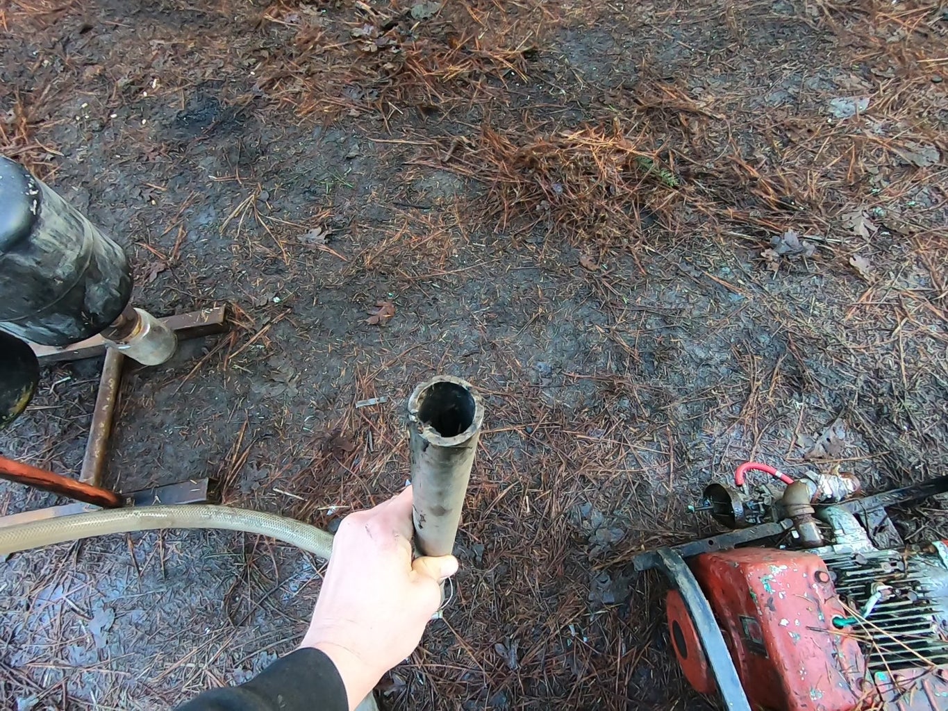
After the blower is just a length of tubing and a piece of metal pipe that's there just there so I can test the gas by seeing if it's flammable before routing it to the engine.
So, we can finally use our gasifier! Starting it up is an easy process and that's what I'll be covering next.
Step 4: Start Up Procedure


The starting of a gasifier is far from rocket science, but it's still vital information. On the top of the reactor is a tube that leads down into the side of the burn tube near the bottom. It's made from 1 1/4" metal pipe that has a coupler and a female pipe plug threaded in to the end for ease of use.
To start the gasifier, simply go in the following order: make sure you have clean and dry fuel in the hopper, remove the ignition port cap, insert something flammable that you can use as a wick, turn the blower on, ignite the wick, leave the cap off until you see the fuel in the grate burning, and then cap it back up. That's it!
As soon as the paper is burning you should see smoke coming from the end of the tube. In an installed gasifier set-up where the gasifier and engine are permanently connected, you'll need one more thing. You need a way to change the direction of the gas between a "flare" that you can vent the gas out of until it's ready for combustion, and the direct path to the engine itself. Mine is very rudimentary so I am literally just sticking the pipe into the air intake when it's ready haha. But it works!
Lastly, you'll need a pre-carburetor. This is just a valve set up mounted to the original engine carburetor. It's just a valve and a "tee" in the line that connects the gasifier outlet to the intake. On that tee is another valve. You use these two valves to adjust the mix of fuel and air to get the mixture just right for running the engine as optimally as possible. It also acts as a vent to let gas keep flowing when the engine is in the other 3 cycles of the 4 cycles that a 4-cycle engine uses.
It's worth noting here that gasifiers are not limited to just 4-cycle engines. As far as I know, you can run any internal combustion engine on syngas. Diesel, 4-cycle gas, 2-cycle gas (as long as you keep the engine lubricated,) and probably even a rotary engine!!!
Step 5: In Conclusion


We've reached the end of our journey! I had a lot of fun putting this together for you guys to see and hopefully you enjoyed it! I went into just about everything that's within my capability, so I hope I was thorough. If you have any questions or comments then please don't hesitate to leave a comment! I love your feedback! I hope I was able to peak your curiosity and maybe give you one more project to add to your list!
I'm trying to start up a YouTube channel that I'm hoping will gain some traction so if you'd like to see this kind of stuff consistently then I would greatly appreciate a "Like" and a subscription over on the channel here.
Here's the link to the FEMA publication as well! It's a wealth of information!
Thank you all so much for your time and I hope this was worth it!
-Tate

Participated in the
Reuse Contest


