

Introduction: DIY Active Subwoofer


Hi everyone! Thanks for tuning in to this project of mine, I hope you'll like it and perhaps try to build it yourself! As always I have included a detailed list of modified plans, a wiring diagram, product links and much more for your information on the build. I encourage you to check my video first before diving in to the build. Let's get started!
Step 1: Design Goals and Plans


The main goal for this project was to build a subwoofer that would play pretty low and would have an integrated amplifier capable of powering two other speakers all cramped inside a relatively compact enclosure. Fiddling around with various woofers in winISD I have decided to go with a Tang Band woofer and a 2.1 amplifier for best results. As you can see by the graph, the enclosure is tuned to 43Hz and has an F3 of around 37Hz which is pretty amazing considering the price of the woofer and the compact enclosure that it needs. Of course it will not play that low cleanly due to port noise and possible chuffing but will still perform great.
As you can see below, I have attached a set of plans, metric and imperial for all needs. You will also find the template for the control panel in the end of the plans which you can print out and glue to a piece of wood to have an accurately made control panel. Feel free to download the plans and the wiring diagram for your personal use. I would love to see how your project turned out!
Note that I have modified the plans therefore the speaker may look different than in the video. I have modified the plans to use less components and be easier to build with an overall better design.

Step 2: Parts and Materials


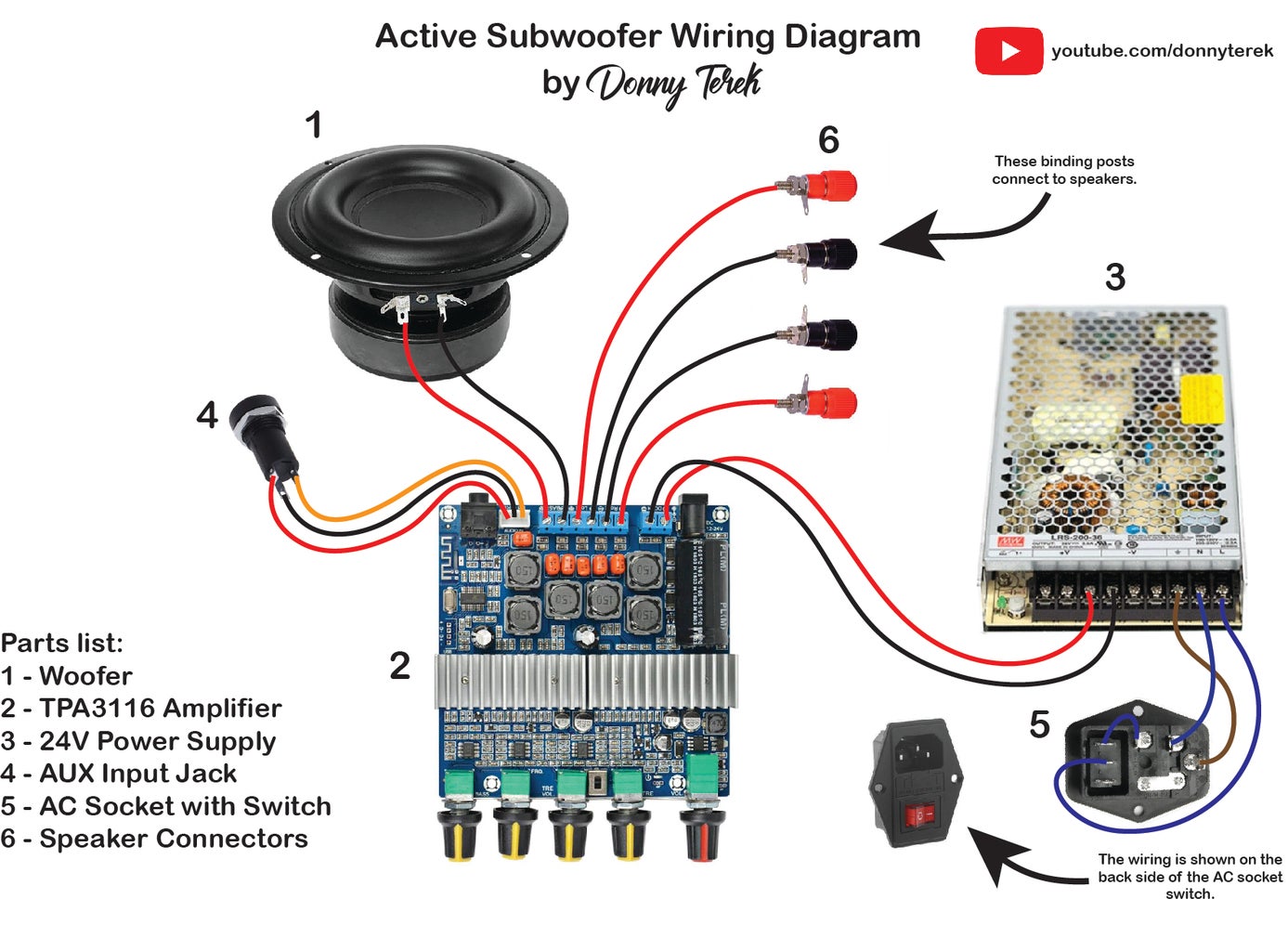
You may have noticed that there are less components in the wiring diagram compared to the video. I did so to reduce the number of the components used and simplify the overall build process of the subwoofer. I have also used a similar amplifier that has the Bluetooth built in so that you don't need a separate module for that. Here you will find the complete list of parts and tools used for the build. Note that the parts can be ordered internationally.
Parts:
- Tang Band W5-1138SMF subwoofer (US/EU) - https://parts-express.sjv.io/a1yN5M / https://bit.ly/3GKCum6
- 150W 24V DC Power Supply - https://parts-express.sjv.io/QOBNMz / https://bit.ly/3XgvDpU / https://bit.ly/3VUmvGo
- 2 ports glued end to end - https://parts-express.sjv.io/kj54ad / https://bit.ly/3Iv8b4j
- TPA3116 Bluetooth amplifier - https://parts-express.sjv.io/e4DnAO / https://bit.ly/3WYi8vG or https://bit.ly/3Zg0wwI
🎁 $5 OFF your first App order on AliExpress - https://a.aliexpress.com/_mPN8FLo
- AC input socket - https://bit.ly/3y77DZU / https://geni.us/iLxkjo
- Banana connector sockets (2 pairs) - https://bit.ly/3Zo6Mmj / https://geni.us/tfFNA
- Audio input jack - https://bit.ly/3GMsgly / https://geni.us/BNMj
- MDF sealer - https://geni.us/9YyKv
Tools:
- TS101 soldering iron - https://bit.ly/3hQm4PP / https://geni.us/owyDm5G
- Multimeter - https://bit.ly/3VOFjYv / https://geni.us/UmrhyYk
- Hot glue gun - https://bit.ly/3QdYfhg / https://geni.us/1dwxqIM
- Wire stripper - https://bit.ly/34kBgLn / https://geni.us/6epIs
- Cordless drill - https://bit.ly/2UiMSbL / https://geni.us/A5AZi
- Jig saw - https://bit.ly/3GpY8w6 / https://geni.us/D8GC
- Drill bit set - https://bit.ly/3S3i6zC / https://geni.us/ktAK1M
- Step drill bits - https://bit.ly/3eM5GtB / https://geni.us/xYRx7J
- Forstner bits - https://bit.ly/35snpjW / https://geni.us/F6it
- Hole saw set - https://bit.ly/3YZU8tg / https://geni.us/hONP
- Wood router - https://bit.ly/3I7Aplm / https://geni.us/6okRl
- Roundover bits - https://bit.ly/3ijBZWU / https://geni.us/cc82
- Center punch - https://bit.ly/3xslc8u / https://geni.us/o5WBEwB
- Helping hand - https://bit.ly/3B9mIgt / https://geni.us/Yyqyte
The main building materials that I used are 12mm (1/2"), 6mm (1/4") MDF boards for the enclosure and 4mm (1/8") plywood for the control panel.
Step 3: Let's Start the Build!

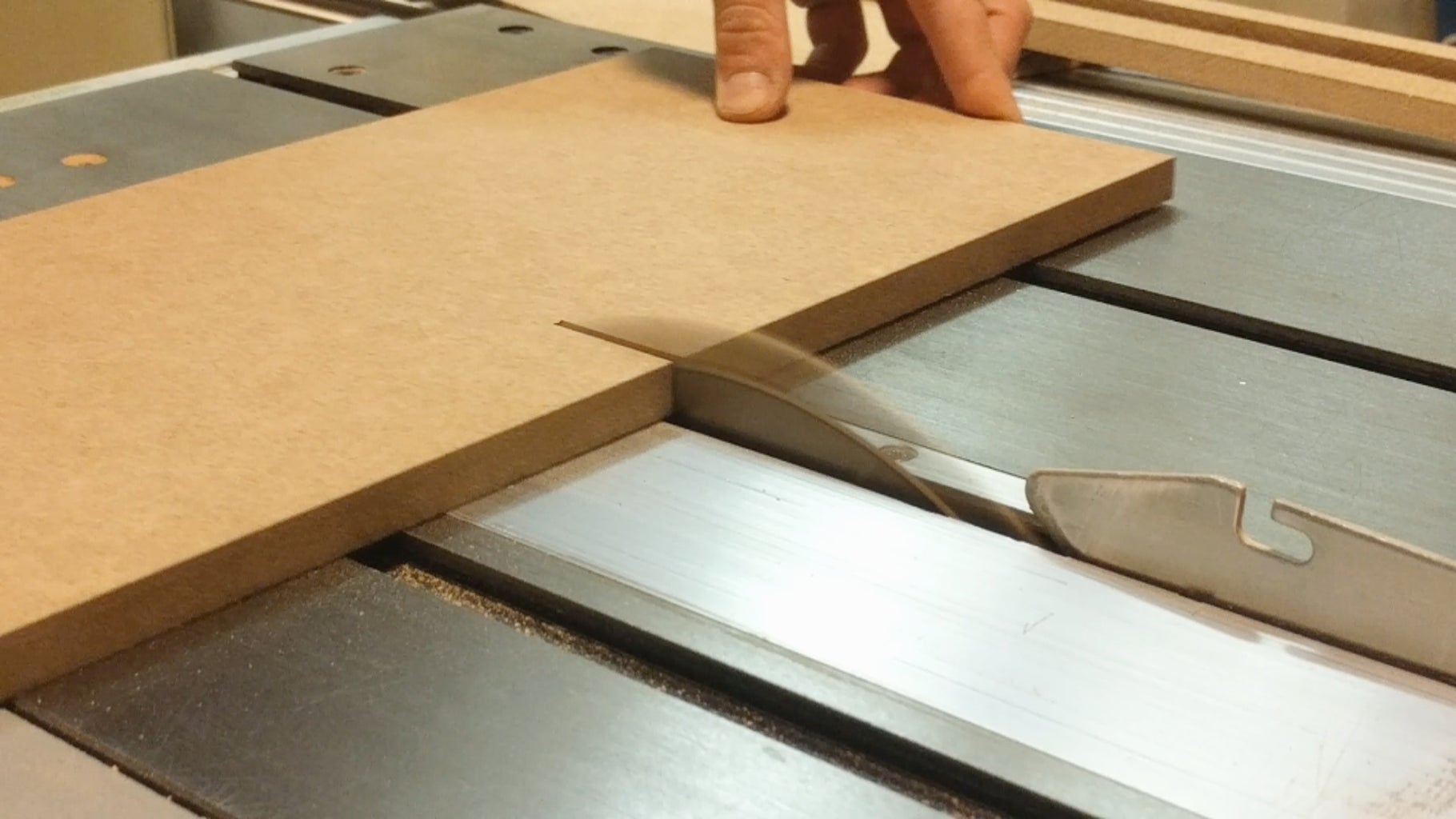


Once you got the plans printed out we can start the build. As you can see I am using a table saw to accurately cut the MDF pieces out but I know that not many people have an access to a table saw. Therefore you can also use a jigsaw to roughly cut the pieces out and sand them down later and perhaps use a bit of wood filler to get the edges as smooth as possible.
To cut out the piece for the amplifier to go through, I first marked the location of where I need to cut out and drilled four holes in each corner, making sure to only drill halfway through on each side to avoid tearout. I then took a jigsaw and cut as close to the line as possible. No need to be exact here, it is only important that the amplifier support panel sits nicely on the edge. I also cut a hole for the port using a circle cutting jig on a router but you can use a 64mm (2 1/2") hole saw so that the port sits snug.
Step 4: More Cutting


Once the side panels were cut I glued the the port in place. Here I am using a PVC pipe as a port since I did not have the proper one on hand therefore I glued the port in place before assembling and painting the enclosure. You should use these ports and glue both of them end to end. Make sure you insert one first through the hole on the side panel and then glue the other port to the first once you have finished the enclosure in your desired paint or material.
I also cut the hole for the woofer with a recess to flush mount the woofer but you can simply cut the hole with a 127mm (5") hole saw and not worry about the flush mounting.
Step 5: Glue Up!


A self-explanatory and satisfying step - gluing the enclosure together. Use plenty of glue on the sides and make sure that the edges are square. Note that I have glued port supports on the bottom of the enclosure which I have not included in the plans - that is one more thing I have redesigned in the final plans so that there is less cutting and the power supply can be mounted on the bottom instead.
Clamping the enclosure together is recommended for best adhesion while the glue dries.
You have also probably noticed that I have glued the back panel support pieces along the back edge of the enclosure but since I have redesigned the speaker, you will need to cut a larger back panel and skip the panel support pieces and screw the back panel directly to the enclosure.
Step 6: Sanding and Smoothing


Once the glue has fully dried I took an orbital sander for a quick job of sanding the enclosure and getting it ready for paint. A sanding block can be used as well but will take much more time and effort so use any help you can to speed up the process.
Once the edges were smooth I took the enclosure and rounded over the edges on the router using a roundover bit. It turned out really nice with a nice radius all around the edges. Sandpaper can be used instead for a similar result.
Step 7: The Back Panel


Notice that the back panel sits differently than in the build plans above. In the redesigned plans you can see that there are no panel support pieces, simplifying the build process so that the back panel can be screwed directly to the enclosure.
I have decided to drill countersinks on the back panel so that the screws sit flush. I then placed the back panel in place and drilled the screw holes. Make sure you drill with a smaller drill bit first all the way through and then use a larger drill bit only on the back panel so that the screws don't bite into the back panel but only clamp it in place.
Holes were then drilled for the AUX input jack and the speaker terminals. I also drilled the holes for the rubber feet and placed 4 screws on the bottom to serve as stands while painting.
Step 8: Preparing for Paint


To prepare the MDF for painting, I made a mixture of 50/50 wood glue (Titebond III) and water and brushed it on the surface letting it cure overnight. This makes the surface hard and great for spray painting later. Once the glue mixture has dried I lightly sanded the enclosure once again to get it ready for painting. Before spray painting I wiped the enclosure with a solvent to remove any oils or residue that may have been left on top.
Step 9: Applying the Paint


I applied a few light coats of grey primer on the surface. Once the primer has fully dried I sanded it with a 600 grit sanding sponge for better paint adhesion. I recommend wiping the surface once again with solvent to remove any oils before painting the color.
I used matte black spray paint for the top color coat, making sure it fully dries afterwards. I am using a heating lamp to speed up the process.
Step 10: Making the Control Panel


To make the control panel make sure you download the plans placed above and use the last page to cut out a template. Double check with a ruler that the measurements are correct on the template once you print it out. You may need to resize the image to get the correct size.
Simply cut out the template and glue it to the plywood piece. Mark the holes with a center punch and use a small drill bit to drill all the holes first. Then gradually use larger drill bits where needed to avoid tearout. Once the holes are drilled take the template off and sand it smooth. I also applied clear coat on the panel for a nicer finish.
Step 11: Mounting the Amplifier


Take the finished control panel and mount it to the amplifier. I have also soldered a green power indicator LED and pushed it in from behind. I then placed the threaded inserts in the amplifier support panel and glued it in place on the ledge of the enclosure making sure that the triangular pieces are also glued in place. I then pushed the amplifier in place, screwed it in from the inside and drill the holes for the screws.
Step 12: Last Steps


Just a few more things left to do and we have a finished active subwoofer! I am placing a strip of adhesive foam around the edge of the enclosure to make it airtight once the back panel is screwed in place. Same goes for the control panel opening. Once that is done I mounted the speaker connectors and screwed the back panel in place. Don't forget to add the rubber feet on the bottom!
Step 13: Mounting the Woofer


Probably my favorite step of this build is mounting this beefy woofer in its place. For that put it in place first and used a hole punch to mark the holes for the screws. I then took the woofer out and drilled the holes through the panel. Using the same adhesive foam tape to make sure the woofer sits sealed against the edge. I ten connected the woofer to the amplifier and screwed it in place. Placing the amplifier knobs finishes the build.
Step 14: Finished!


We can sit back and admire the little subwoofer that we have built. Just plug in the power cord, turn on the switch and use your preferred method of audio input - whether it is through an aux cable or Bluetooth. The Bluetooth connection is instant and stable, providing great sound and performance.
Step 15: Final Thoughts

I am more than happy this subwoofer turned out. It packs a punch and is definitely powerful enough for home use. It can also output plenty of power to various different speakers for the best listening experience.
I hope you liked this project and perhaps learned something new! My hopes are that you will give this build a try yourself and post it at the end of the Instructable so that me and others can admire your work! Feel free to post any questions or comments down below, I will try my best to answer them.
Thank you for tuning in to this project of mine and I will see you on the next one!
- Donny

Participated in the
Woodworking Contest


